
PrusaSlicer Modifier Mesh: Strengthen Only One Area of a Part
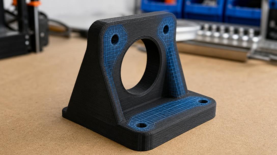
A PrusaSlicer modifier mesh lets you apply different print settings to only the section of a model you choose. This allows you to reinforce load-bearing areas such as screw holes, clips or attachment points, while avoiding unnecessary increases in material use and print time elsewhere on the part.
What is a modifier mesh used for?
A modifier mesh is auxiliary geometry placed inside the main model to change slicing settings within a defined volume. It is not used to alter the part’s outer shape; instead, it lets you adjust values such as wall count, infill density or print speed in the area it covers. For example, you can reinforce the screw bosses on an enclosure or add more material around a corner where loads concentrate on a fixture.
This approach can be more targeted than printing the entire part with thicker walls or a higher infill percentage. However, strength does not depend on infill alone: part orientation, wall continuity, material and the bond between layers all affect the result.
How to set up regional settings in PrusaSlicer
- Add the model and modifier geometry. Open the main model in PrusaSlicer, then add a cube, cylinder or suitable mesh to use as a modifier. Position and scale the modifier volume so that it covers the area you want to reinforce.
- Assign the modifier function. Select the auxiliary geometry in the object list and define it as a modifier. Menu names may vary depending on the version and interface layout, so confirm the modifier type in the object properties.
- Change only the settings you need. In the modifier-specific settings, you can increase the number of wall loops or the infill density. For example, adding more walls around a screw boss is often a more meaningful starting point than simply increasing the internal infill percentage. There is no single setting that works for every model; take the part’s loads and geometry into account.
- Inspect the sliced preview. Check that the change has been applied to the correct area, that the modifier volume has not created unwanted gaps, and that the layer paths remain continuous around the connection. If needed, expand the modifier boundary or adjust its position.
Common mistakes
- Making the modifier too small to fully cover the critical area.
- Assuming that increasing the infill percentage alone will be enough without adding more walls.
- Assuming the setting has been applied correctly to every layer without checking the model preview.
- Trying to solve the problem with slicer settings alone while ignoring layer orientation and connection geometry.
If the part has a screw boss, clip or thin arm, first identify where the force is coming from. Adding rounded transitions and sufficient wall thickness to the design may be more effective than increasing local infill. If the part is separating along the layers in its print orientation, consider changing the model’s orientation or redesigning its geometry as well.
When should you use it?
A modifier mesh is useful when loads are concentrated in a small, defined area of a part and you do not want to make the entire model heavier. If the same reinforcement is needed across a large area, changing the model’s own settings may be easier to manage. Once the design and production requirements are clear, the file’s printability can also be assessed as part of the online 3D printing service process. If you are unsure about the part’s material or geometry, you can share details about the file when requesting a 3D printing quote and consultation.
To understand the basics of the modifier approach, you can explore how a slicer converts model settings into print paths. The best results come from considering regional settings together with the load-bearing geometry and print orientation.


 Türkçe
 العربية
 Русский
 فارسی
فارسی Deutsch