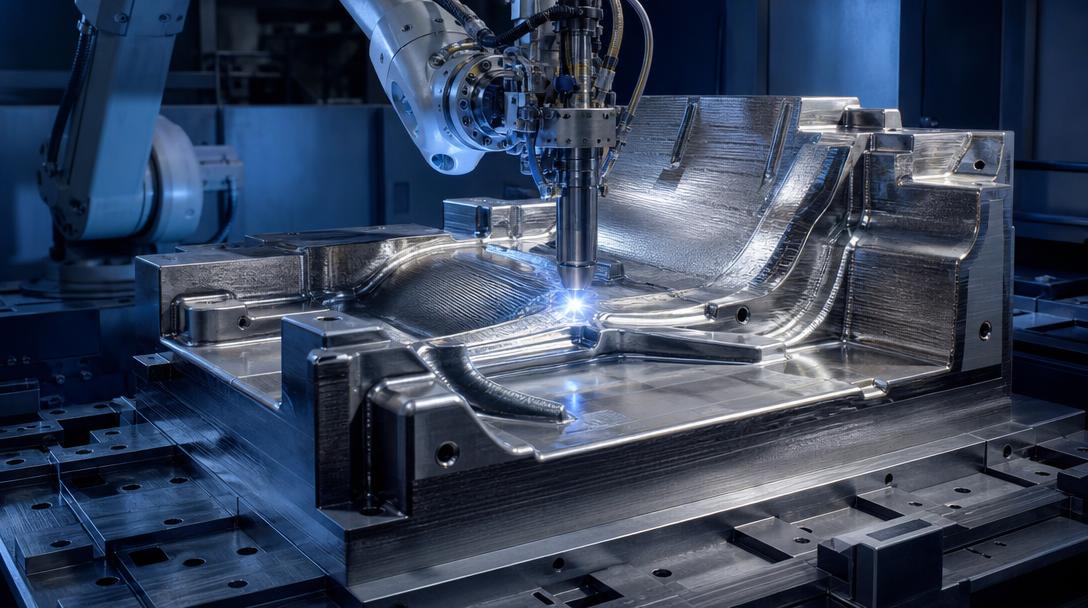

ORNL and Boeing Produce a 2-Ton Aircraft Composite Mold Using WAAM
WAAM 3D printing is being tested in aerospace as an alternative way to produce large metal tools. Oak Ridge National Laboratory (ORNL), part of the U.S. Department of Energy, and Boeing produced an approximately 2-ton Stamp Form Die using wire arc additive manufacturing, contributing to NASA’s HiCAM program. The project shows that 3D printing is being considered not only for small prototypes but also for large production tools.
A mold for aircraft door production
The mold produced through the joint ORNL–Boeing project measures approximately 6 × 4 feet and is made of steel. Boeing plans to use this tool to manufacture thermoplastic aircraft doors. These parts are made by shaping heated plastic between two molds. NASA’s HiCAM initiative covers efforts to increase the production rate of composite aircraft parts.
Tools of this kind can traditionally be made using methods such as machining, casting, forging, and drilling. The question the researchers are testing is whether 3D printing can produce a mold with controlled thermal channels more quickly, at lower cost, or more easily. This report is not proof that the method has definitively achieved these goals in serial production; it is an example of a collaborative project exploring alternative tooling methods.
Why was WAAM chosen?
The system used by ORNL is based on wire arc additive manufacturing (WAAM), a process that melts wire feedstock with an electric arc and deposits the material layer by layer. Using a robotic arm and welding torch, this process offers an approach suited to producing large metal geometries. ORNL also says the system can feed multiple metal wires together, allowing different materials to be used in a single design.
The mold made for Boeing uses mild steel in structural areas for strength and rigidity, and stainless steel on the mold surface for corrosion resistance and working-surface properties. The multi-material design demonstrates that the same metal does not have to be used throughout the entire part. However, assessing its real advantages requires comparing production time, post-processing requirements, mold life, and performance under operating conditions with conventional tooling. Additively manufacturing a large part does not eliminate the need for subsequent machining and dimensional inspection. In particular, the shape of the mold surface, the quality of areas that contact the part, and how heat is managed throughout the process are important for final use. For this reason, choosing a production method requires considering the part’s entire life cycle, not just the printing stage.
What FDM workshops can learn
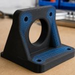
WAAM is an industrial process that uses metal wire and an electric arc; it is not the same technology as desktop FDM printing. Still, the example offers a shared lesson for production teams: the tool’s size, function, and load conditions should determine the method. While metal deposition may be worth considering for a large, heavy mold, FDM may be a more accessible option for an assembly jig, enclosure, ergonomic prototype, or low-load auxiliary fixture. In either case, it is important to design the part for its intended use and validate it before production.
- Define the function first: Are you making a mold, an inspection fixture, or a prototype?
- Consider scale and load together: Large size alone does not make additive manufacturing the right choice.
- Factor in post-processing and service life: Post-print machining and maintenance affect the overall production decision.
You can explore your FDM-manufactured part and prototype needs through our 3d baskı hizmeti and get information about ucuz 3d baskı fiyatları using your design file. You can also upload your file to calculate a 3D printing price instantly. To compare materials and operating conditions for an engineering part, explore our mühendislik malzemeleriyle baskı options, and see our guide on baskı yönünün parça dayanımına etkisini during the design stage.


 Türkçe
 العربية
 Русский
 فارسی
فارسی Deutsch