
FDM Rib Design: How to Increase Part Stiffness While Using Less Material
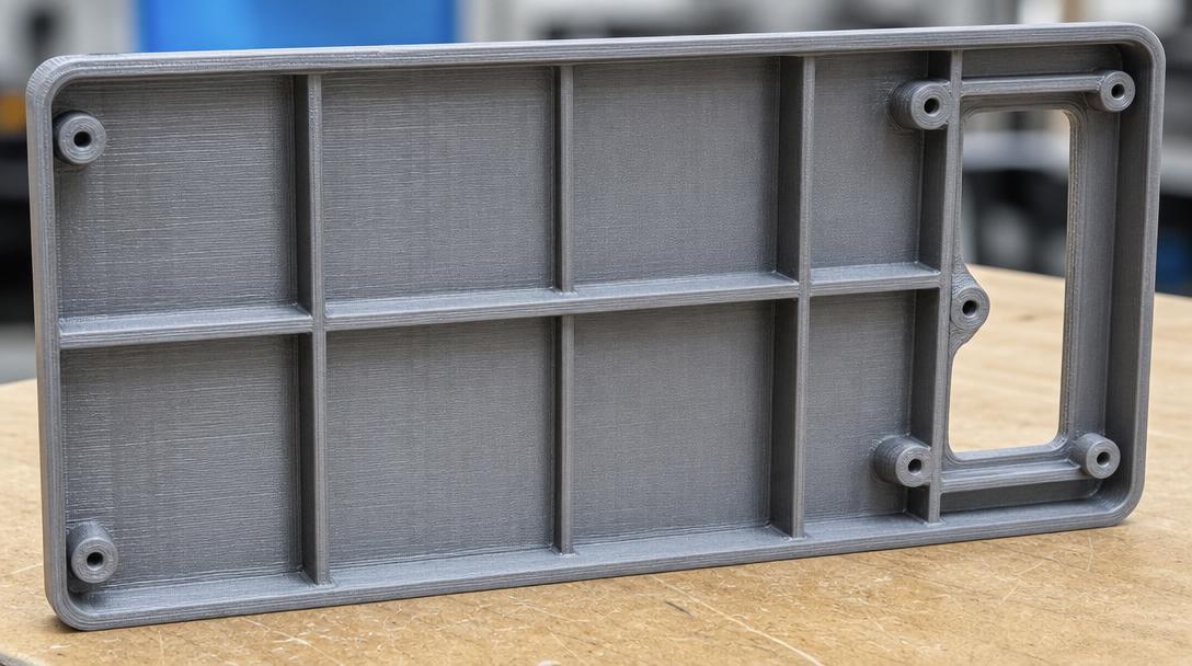
FDM rib design can help increase part stiffness without thickening a large, thin surface everywhere. Ribs can limit flexing by deepening the cross-section of a load-bearing surface; however, their position, dimensions, and print orientation should be chosen to suit how the part will be used. Otherwise, the added geometry may increase material use and print time without providing the expected support.
When are ribs useful?
If a cover, enclosure wall, or large panel flexes under load, consider adding ribs along the direction of the load instead of thickening the entire surface. A rib deepens the surface cross-section, increasing its resistance to bending. This approach can be especially useful when a lightweight body needs to retain its shape or flexing around a connection needs to be reduced. Rather than adding the same amount of material to every part of the component, ribs let you direct support along the lines where it is needed.
First, determine the direction of the force on the part and where it flexes. Position the rib along the path through which the load is transferred to a support or connection point. Adding many thin lines at random may not support the actual load path; the design should have a specific purpose. If the part is loaded in multiple directions, do not assume that a single rib layout will meet every requirement. Consider the primary loads together with the points where the part is supported.
How do you design ribs for FDM?
- Soften the junction with the base: Using a small fillet instead of a sharp inside corner where the rib meets the main wall can help reduce an abrupt change in geometry. This transition also makes the model easier to inspect in the slicer.
- Avoid unnecessarily thick walls: Start with a rib thickness that is compatible with the part’s overall wall structure. A rib that is too thick may cool differently from the surrounding wall, leaving marks on the surface or causing local distortion. Size it according to the part’s actual needs; do not assume that larger geometry is automatically better.
- Account for print orientation: The bond between layers may not behave the same way in every direction. If the load acts in a direction that separates the layers, adding a rib alone may not be enough; evaluate the print orientation and geometry together. If possible, consider orienting the part so that important loads are carried in the layer plane rather than pulling the layers apart.
- Choose printable dimensions: Very thin ribs may disappear in the slicer or print inconsistently. Check the model in the slicer to confirm that the rib is actually generated and connects properly to the main wall. If the layer preview shows gaps, broken lines, or unexpected wall thickness, correct the geometry before printing.
- Set the spacing according to function: Before increasing the number of ribs, check which areas the existing layout supports. Elements that are too close together can make the design unnecessarily complex, while spacing them too far apart may fail to prevent unsupported surfaces from flexing.
Ribs or thicker walls?
If the load is distributed across the entire surface or the part is subject to impact and wear, adding ribs alone may not be the right solution. Local support around a connection, a corner fillet, or a change in wall thickness may be more appropriate. If the goal is to reduce the part’s mass and production time, ribs may be preferable; if simplicity, impact resistance, or preserving internal volume is the priority, thicker walls may be a better choice. Make the decision based on the part’s actual operating conditions. Preserving the internal space may matter in a closed enclosure, while a connection point may require more material.
For a prototype, print test samples with different rib orientations and spacing. Apply a similar load to each sample at the same point, then compare flexing, crack initiation, and behavior around the connections. Keeping the test conditions as consistent as possible helps you see the effects of design changes. If you are also designing interlocking parts, the guide to tolerances and fit design can help you assess clearances.
Preparing the model for production
Adding ribs does not, by itself, validate the model. Consider the part’s load, operating environment, material selection, and print orientation together; test a prototype under conditions close to actual use if the part has a critical function. After designing the rib geometry, check how the walls and junctions form in the sliced layers. Before sending your file for production, you can assess whether the model is printable through the online 3D printing service; if you need cost information, you can use the 3D printing price calculator.



 Türkçe
 العربية
 Русский
 فارسی
فارسی Deutsch