
How to Measure Fit Clearance with an FDM Tolerance Test Cube
An FDM tolerance test cube helps you determine whether two parts designed to fit together will sit tightly, comfortably, or loosely by measuring their clearance. The most reliable way to find your printer’s actual tolerance is to print a small test part with different clearance values and measure the fits.
Why isn’t tolerance a single fixed value?
The dimensions in a CAD model and those of the printed part can differ depending on the material, print orientation, layer settings, and machine calibration. Horizontal holes also often print narrower than their design dimensions, while external dimensions may deviate in a different way. For this reason, transferring a fit clearance that works on one printer directly to another may not produce reliable results.
Decide on the type of fit first: parts that do not need to be removed call for a tight fit; covers that will be put on and taken off by hand need a sliding fit; and moving parts that require clearance need a looser fit. Testing with the same material and a similar print orientation to those you plan to use for the actual part will make the results more meaningful. Also consider the part’s end use and the force that will be applied during assembly.
How do you prepare the test part?
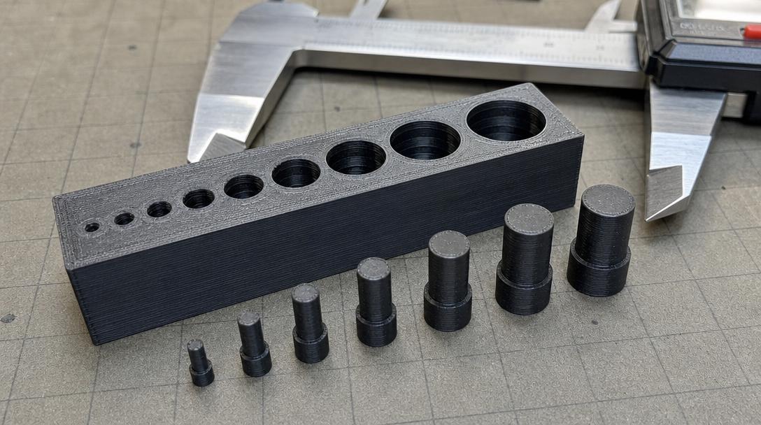
- Design a simple mating test. Use a small model with holes or slots of different diameters in a base, along with matching pins. Make sure each pair has a distinct nominal clearance that is easy to identify.
- Choose a range of clearances. For example, test values starting at 0.10 mm and increasing in small increments. These ranges are only for designing the test; they do not guarantee results that will apply to every machine and material.
- Keep the print conditions consistent. Print the part without changing the layer height, number of walls, flow setting, or print orientation. Changing multiple settings at once during a test makes it difficult to tell which factor affected the result.
- Test the parts in a controlled way. Insert the pins into the slots without forcing them. Note which pairs do not fit at all, which require noticeable force, and which move easily.
Interpret the results correctly
Choose the smallest clearance that provides the fit required for the part to function, but also evaluate the part under its intended conditions. A cover that is opened and closed frequently may need to fit comfortably. Too much clearance in a load-bearing joint, however, can cause it to wobble. Checking dimensions with calipers is useful, but remember that the force applied when measuring small, flexible parts can affect the measurement.
If the test pins consistently fit too tightly or too loosely, check flow and dimensional calibration before adjusting the model tolerance. Making a different compensation for every model can hide a problem with a fundamental machine setting. When designing a dimension-critical part, the manufacturability principles in the design guide for 3D printing can also help.
From the test to the actual part
Record the test results: material, print orientation, layer height, chosen clearance, and how the fit feels. This record provides a starting point for similar parts printed later with the same settings; it is still wise to run a small verification test when using a new material or a different orientation.
When applying the test results, also consider the part’s size, print orientation, and assembly method. A small test cube may not fully represent how every area of a long or complex model will behave, so critical joints may need to be tested separately.
To estimate the production cost of a custom-sized part, you can use the 3D printing price calculator, and learn the basics of fit design in the tolerance guide for interlocking parts. A small test can make design decisions more predictable by reducing the need to reprint the entire part.


 Türkçe
 العربية
 Русский
 فارسی
فارسی Deutsch