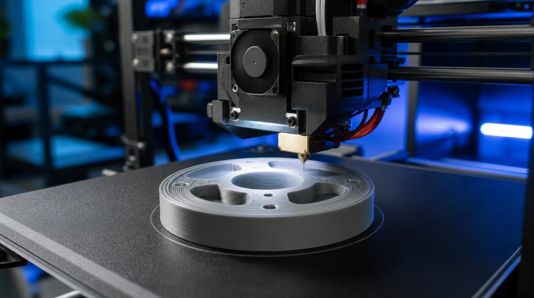

Arc Welder G-code Reduction: Smoother Curves and Smaller Files
Arc Welder G-code reduction can reduce file size and make printer movements smoother, especially in curved models made up of many small lines. The plugin converts closely spaced straight-line commands into G2 and G3 arc commands, allowing the same geometry to be defined with a shorter sequence of commands.
What does Arc Welder do?
When an STL file is sliced, curved surfaces are often represented by many short line segments. The slicer writes these segments into the G-code as separate movement commands. As the curvature of the model increases, so does the number of commands; this can unnecessarily inflate the file, require the control board to process more commands, and cause movement to proceed in small start-and-stop steps on some printers.
Arc Welder reduces this repetition by converting suitable sequences of lines into arc movements. The result may not be the same for every model; however, a noticeable difference can be seen especially in circular holes, cylindrical bodies, rounded corners, and curved decorative surfaces.
Why does the G-code file become smaller?
In G-code, a straight line is generally stored as a movement command defining its start and end coordinates. When a curved surface is divided into many short lines, it may require dozens or hundreds of commands. Arc Welder combines geometrically compatible commands into a single arc movement.
- Fewer commands: The same curve can be expressed with a shorter G-code sequence.
- Smaller file: Transferring the file to the control board and processing it may become easier.
- Smoother movement: The printer may need to change direction continuously less often between short lines.
- More consistent curves: Motion continuity may improve, especially along circular contours.
What should you check before using Arc Welder?
This tool does not fix a poorly modeled or incorrectly sliced file. First, the model’s surfaces should be closed, the STL export resolution should not be unnecessarily low, and the slicer settings should work correctly. Applying arc fitting to a very low-resolution model can cause unexpected deviations in curves.
In addition, the printer’s firmware must support G2 and G3 arc commands. On unsupported systems, it is not advisable to start printing directly without checking how the commands will be interpreted. It is safer to make the first attempt with a small cylinder, ring, or curved test model.
Practical workflow
- Prepare the model normally in the slicer and create the G-code file.
- Keep a copy of the original file.
- Apply the conversion with Arc Welder.
- Check the size and command structure of the new file.
- First, make a small test print and compare the outer surfaces, circular holes, and dimensions.
At this stage, a reduction in file size alone does not guarantee quality. You should also observe dimensional accuracy on curves, movement behavior at corners, and surface continuity. For technical parts, critical hole and fit dimensions should be checked with calipers after the test print.
When preparing your model for printing, setting up the basic slicer and slicing settings correctly directly affects the result you get from Arc Welder. To assess the FDM manufacturability of the prepared part, you can review the 3D printing service options and see the production cost using the instant price calculator.
With the right model, compatible firmware, and a controlled test print, Arc Welder can be a practical aid for improving file management and motion flow, especially for curved FDM parts.


 Türkçe
 العربية
 Русский
 فارسی
فارسی Deutsch