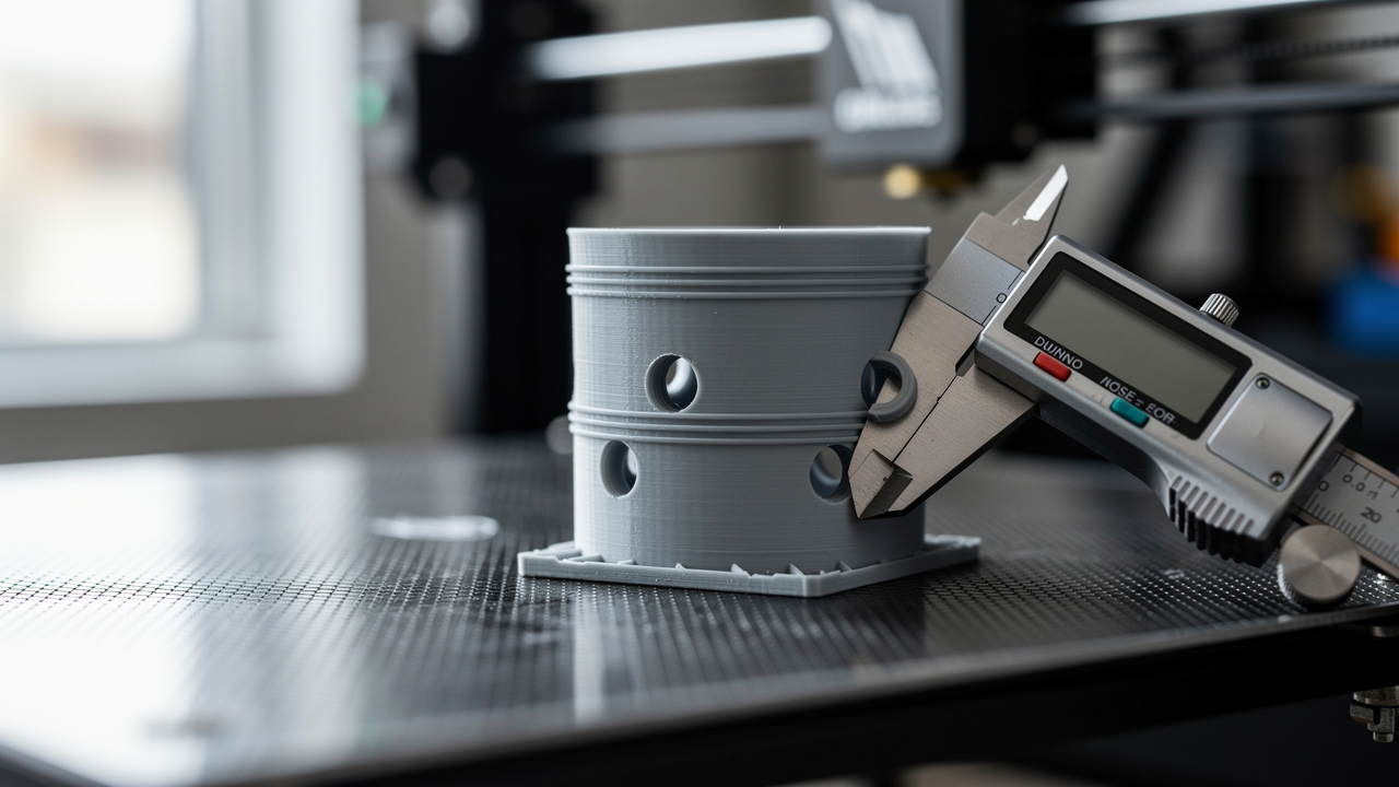

Why Is Hole Compensation Necessary in 3D-Printed Parts? How Is Horizontal Hole Compensation Done?
Hole compensation in 3D printing parts is often a mandatory design step, because especially in horizontal holes, layer geometry and material flow cause the diameter to come out narrower than the nominal dimension. For this reason, in parts where a screw must pass through, a shaft must fit, or a cable route is needed, models designed without considering compensation often require rework in real-world use.
In parts produced with the FDM method, the issue usually does not come from the printer being “faulty,” but from the fact that the melted filament is laid down not as a perfect circle but as a slightly flattened line. When layer bridging at the top of the hole, slight inward bulging, and cooling behavior combine, a hole drawn as 5 mm may measure 4.7–4.9 mm in print. Especially in electronic enclosure 3D printing parts, this difference directly turns into an assembly problem in button, screw, and connector seats.
Why do holes become more problematic especially on the horizontal axis?
From the printer’s perspective, a horizontal hole is not a perfect circle; it is a geometry whose bottom is supported while the top is partially suspended in air. In the upper half of the hole, the layers behave like a small bridge. If the nozzle is too hot or the fan is insufficient, this section sags slightly. If a high flow rate is added on top of that, the hole starts closing inward.
- Excess flow: Even if the drawing is correct, the hole becomes narrower.
- High nozzle temperature: The material spreads, and the edges do not stay sharp.
- Insufficient part cooling: The upper arch shape is distorted.
- Layer height and line width: The result deviates more noticeably in fine-detail holes.
- Part orientation: The same hole may print more accurately when vertical and become more problematic when horizontal.
How is practical hole compensation done?
The safest method is to print a small test part instead of using a one-time “universal magic number.” Measure your printer’s actual behavior with a simple sample containing several holes such as 3, 4, 5, 6, and 8 mm. For example, if a 5 mm hole consistently prints at 4.8 mm, it makes sense to consider 0.2 mm compensation in the design.
The general starting approach is this: for holes that need a free fit, add +0.15 to +0.30 mm to the diameter; if a screw or pin needs to pass through comfortably, sometimes slightly more clearance is left. However, this value varies depending on PLA, PETG, ABS, nozzle condition, and flow calibration. Before designing the part, the approach in the guide What Is Tolerance? How Should Interlocking Parts Be Designed? is also very useful here, because a hole should not be evaluated on its own, but together with the shaft, screw, or snap-fit detail it will work with.
Should the design be corrected, or the slicer?
Both are possible, but in technical parts that will be produced repeatedly, consciously compensating in the design first gives more controlled results. Settings such as “horizontal expansion” or similar on the slicer side affect the entire model. While this may work well for some parts, if you only want to correct a single hole, it can also distort other surfaces.
If you regularly have enclosures, connection fixtures, or functional prototypes produced, it is healthier to send dimension-critical parts directly into the 3d printing service workflow with a note about test dimensions. This way, not only the outer form but also the hole diameter, screw passage, and assembly tolerance are handled according to the part’s intended function.
When is it more sensible to drill it out afterward?
If function matters more than appearance and the hole axis is not critical, leaving a small pilot hole and achieving the final size with a drill is a good solution. This method saves time especially in parts that do not have a bearing seat and only need screw clearance. On the other hand, in electronics covers, snap-fit assemblies, or repeating production parts, achieving the correct dimension during printing gives a more professional result.
In short, holes coming out undersized is a common behavior in FDM; the solution is not random enlargement, but controlled compensation according to the material and use scenario. In a technical part, planning dimension-critical regions correctly from the start is far more efficient than dealing with sanding and drilling afterward.


 Türkçe
 العربية
 Русский
 فارسی
فارسی Deutsch