
How to Design a 3D-Printed Drilling Jig? A Practical Guide for Repetitive Jobs
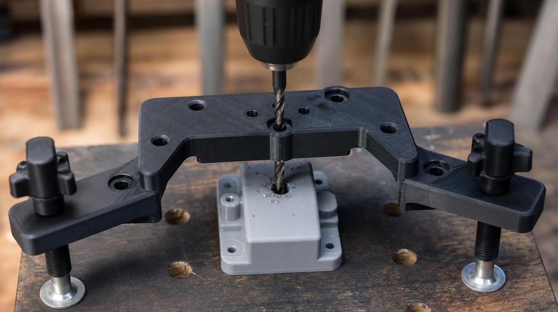
Delme jig 3d baskı is one of the most practical solutions when you need to drill the same hole in the correct place again and again. In wood, plastic, or thin metal work, instead of remeasuring the part every time, you can use a guide that fixes the measurement in place to both shorten the process and reduce the margin of error.
What exactly does a drilling jig do?
A simple drilling jig is an auxiliary part that keeps the drill bit’s position, angle, or distance from the edge fixed. It is especially useful in small workshops, low-volume production, and the prototyping stage. In jobs that do not require production-level metal fixtures, being able to test quickly with FDM printing offers a major advantage. If you need such a part, having a sample produced with a custom-size 3d printing service and testing it in the field is often the most sensible place to start.
The first 4 points you should consider in the design
The success of a good jig does not come only from showing the hole location; it also needs to avoid slipping during use, resist cracking, and not force the user into the wrong position. When setting up the design, these four headings are critically important:
- Reference surface: The jig should seat on the part from the same edge or the same corner every time.
- Bushing or guide hole: If the drill will rub directly against the plastic, the hole should be designed slightly thicker and the surrounding area should be made strong.
- Clamping area: A safe surface should be left for a vise, screw, or hand pressure.
- Chip evacuation: Small reliefs around the hole that prevent chips from accumulating improve ease of use.
Especially in auxiliary parts that require a tight fit, giving the correct dimensional tolerance is essential. At this point, the tolerance guide for interlocking parts helps you achieve more accurate results on the first attempt.
Which material and which printing approach are more suitable?
There is no single correct material for a drilling jig. PLA may be sufficient for light use and rapid prototyping; however, if there is impact, heat, and long-term use in a workshop environment, PETG, ASA, or engineering-grade filaments are safer choices. In scenarios where drill friction will be applied directly to the hole, adding a metal bushing inside the plastic body is also a good solution. This way, you can preserve the speed of FDM printing while increasing wear resistance.
Print orientation is at least as important as the material. If the drilling force is applied in a direction that tends to separate the layers, the part will behave weakly. For this reason, positioning the jig so that the print layers are perpendicular to the load direction, increasing the wall count in critical areas, and improving perimeter strength instead of using unnecessary infill is a better approach. To make a decision on the cost side, you can get an instant price for online 3d printing and quickly compare different size and material options.
When is a 3D-printed drilling jig a good idea, and when is it not?
This method makes a lot of sense for prototypes, assembly support tools, low-to-medium volume repetitive work, training workshops, and custom-sized products. Because you can revise the design on the same day, and if you need to shift the hole by 1 mm, you can produce a new version without having to remake the entire fixture. On the other hand, for jobs that require very high drilling force, hard steel drilling, hundreds of repetitions, and micron-level precision, a metal fixture may be the better choice.
In short, producing a drilling jig with FDM offers a strong balance between speed, low cost, and design flexibility. Especially when you need a custom tool or fixture, starting with a 3D-printed version that validates the function gives you a clear basis for decision-making before moving on to more expensive manufacturing later.


 Türkçe
 العربية
 Русский
 فارسی
فارسی Deutsch