
Can a Broken Plastic Part Be Reproduced with 3D Printing? What Measurements Should You Take First?
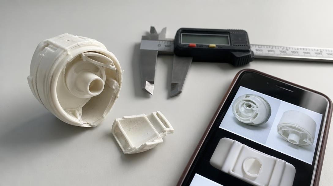
A broken plastic part can often be reproduced with 3D printing, but its suitability depends on its function, the loads it bears and the measurements that can be taken from the sections that remain intact. The best place to start is by photographing the broken part from every angle before discarding it and recording the dimensions of any matching, intact surfaces.
First, identify what the part does
Does the part simply hold a cover in place, or does it support a moving mechanism? Is it exposed to continuous loads, impacts, friction, heat or outdoor conditions? These questions affect not only the geometry, but also the choice of material and print orientation. For safety-critical or high-load applications, you should not assume that a visually similar copy will perform equally well.
The broken surfaces can help you understand how the part fits together, but the fracture area may not be a reliable reference for measurements. If possible, identify the part’s intact edges, mounting holes, tabs and surfaces that contact the mating part. The part’s function and operating environment provide essential information for an initial assessment of 3D printing a broken plastic part.
Record these details when taking measurements
- Overall dimensions: Measure the part’s width, length and height; use calipers if possible.
- Connection points: Note the hole diameter, the distance between hole centres, the depth of any recesses and the direction of the screw.
- Contact with the mating part: Photograph the fitted surfaces, clearance for movement and the direction in which the part is installed.
- Wall thickness and ribs: Measure the wall thickness and supporting features in areas that are not broken.
- Operating conditions: Describe any exposure to heat, sunlight, moisture, chemicals, vibration or repeated loads.
Rather than providing each measurement on its own, take photos from several angles with a ruler or calipers in view. This makes it easier to interpret the part’s shape. If available, the other half of the broken part, a matching symmetrical section or the slot where it fits should also be assessed. Clearance matters when multiple parts fit together; understanding tolerance design for parts that fit together helps set more realistic expectations for the first fitting.
What if you don’t have a CAD file?
Measurements and photos provide a starting point for recreating the part. Basic dimensions may be enough for simple geometries; parts with curves, tabs or multiple mating surfaces may require more detailed modelling or an intact reference part. It may not be possible to determine every hidden dimension with certainty from photos of the broken part alone. Instead of guessing missing measurements, it is better to show the mating part and installation location as well.
Once the model is complete, the print orientation, the direction of the layers relative to the load and any need for supports should also be assessed. These choices can affect the part’s dimensional accuracy and strength; the effect of print orientation on part strength should be considered at this stage.
What information is enough for an assessment?
For an initial review, the part’s intended use, approximate dimensions, photos of its intact and broken surfaces, any matching part and information about its operating environment are usually a good starting point. If you have a model, you can use it for 3D printing price calculation; if not, the first step is to assess whether the part can be recreated from photos and measurements. Accurate dimensions and information about how the part is used help reduce the risk of producing something that looks similar but serves a different function.


 Türkçe
 العربية
 Русский
 فارسی
فارسی Deutsch