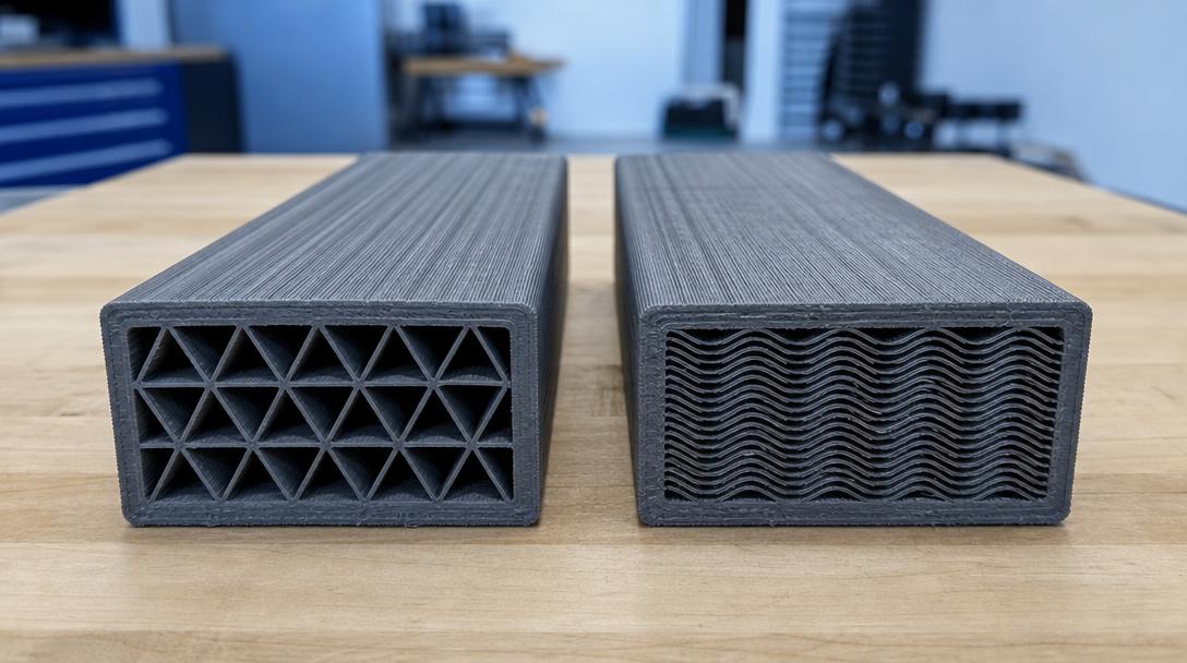

Why Does FDM Part Strength Depend on the Toolpath? Novineer’s New Tests
FDM part strength is determined not only by filament type and model geometry; the toolpath generated by the slicer can also affect the result. A technical analysis by Novineer CEO Ali Tamijani, published in TCT Magazine on October 12, 2026, uses test examples to explain how small differences in print paths can change mechanical behavior, even when the same material and geometry are used.
The same beam, a different toolpath
In the demonstration shared in the article, two beams made from the same material on the same printer, with identical geometry, are subjected to the same load. The difference lies in the paths followed by the infill lines. Tamijani reports that, in the example, one beam deflected up to six times more than the other. This is not a universal factor that applies to every print; it is an observation from a comparison involving a specific geometry and toolpath. Still, it clearly shows that a design is more than just its CAD model.
For this reason, slicer settings should be considered alongside the part’s functional requirements. Load direction, wall placement, infill pattern, and print orientation can all affect how much a part flexes or how much load it can carry in a given direction. Increasing a part’s infill percentage is not always the most efficient way to strengthen it; first, you need to understand where the load comes from and where the part is weakest.
Toolpaths can also affect test results
In another experiment shared by Novineer, Nylon 12CF specimens are compared under shear load using different raster orientations. According to the article, specimens printed with a diagonal, approximately 45-degree toolpath measured 3.5 times stiffer than straight-raster specimens in a specific test setup. This finding comes from testing a particular material and specimen geometry; it should not be directly generalized to other materials or real-world parts.
A further experiment reports that adding a single outer perimeter along the edge increased strength by 60% in the specimens studied. According to the researchers, the perimeter can reduce irregularities caused by filament ends at the outer edge and create a continuous line. This suggests that a small slicing difference can matter under certain conditions. The 60% figure is not a universal design guarantee; it should be considered in the context of the test’s orientation and specimen conditions.
Practical implications for part design
- Identify the load direction: Determine which direction the part will be loaded in during use, then assess the print orientation and layer placement accordingly.
- Don’t overlook the outer walls: The number of perimeters and the contour path can matter, especially around edges and connection points.
- Validate with a prototype: Rather than relying on a single setting for a critical part, print and compare specimens that match the actual direction of use.
- Record test conditions: Note the filament, orientation, and slicing settings to make fair comparisons with future prints.
This approach is especially important for load-bearing FDM parts such as clips, mounting tabs, brackets, and enclosures. To assess the effect of layer orientation during the design stage, you can also read the guide to print orientation and part strength. It is also important to consider FDM printing materials in light of the part’s requirements.
The manufacturing path is a design input, just like the material
The tests reported by Novineer emphasize that slicing settings are not an insignificant step chosen afterward, separate from the material. However, the research findings should not be treated as a direct guarantee of strength: results can vary with changes in part geometry, printer, material, orientation, and test method. The safest approach is to validate a functional part with a prototype and appropriate testing before putting it into production.
To assess whether your part can be produced, learn more about the 3D printing service, check the estimated cost for your file using the calculator on the affordable 3D printing prices page, or upload your model to the 3D printing price calculator to see your price online.


 Türkçe
 العربية
 Русский
 فارسی
فارسی Deutsch