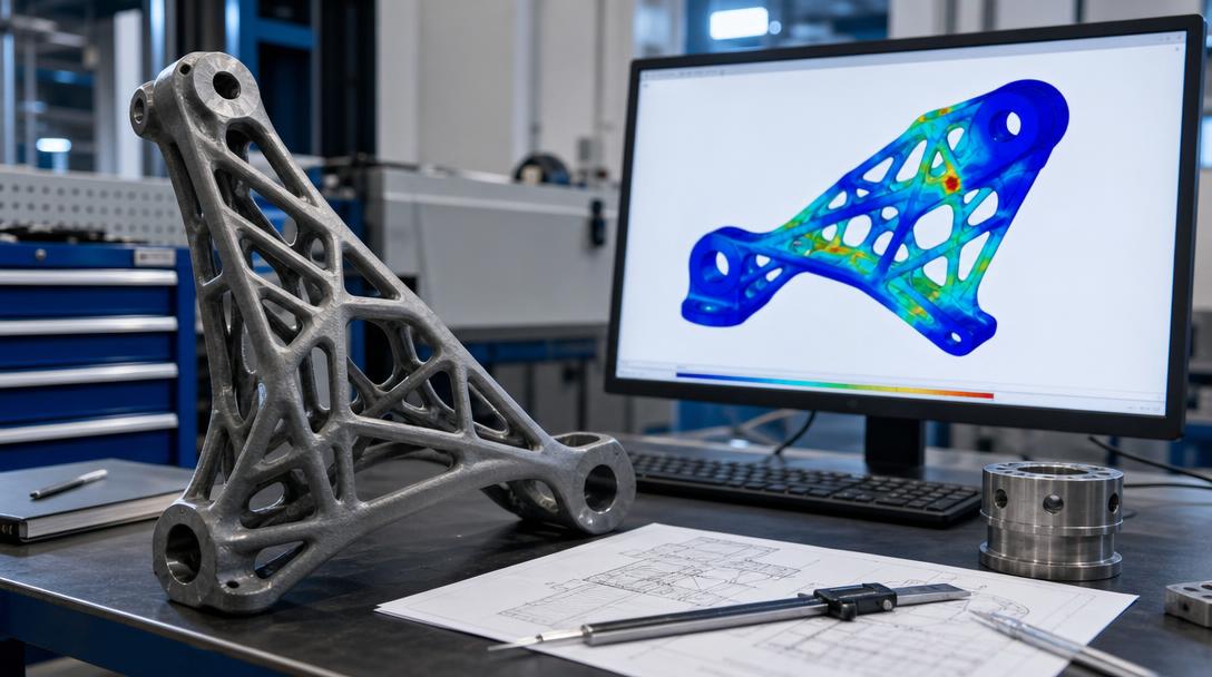

SphereneNXT Brings Structural Simulation into 3D-Printed Part Design
Choosing the infill and lattice geometry for 3D-printed parts can affect not only the amount of material used but also how the part behaves under load. Swiss software developer Spherene has added structural simulation to its sphereneNXT platform, bringing the steps between design and initial analysis together in the same browser-based environment. According to a report by 3D Printing Industry dated October 8, 2026, the feature is available in sphereneNXT v2.0.0.
Design and analysis in the same workspace
The new tool lets users perform linear static analysis while creating a part’s internal structure. Engineers can apply defined loads and constraints to the model, then examine stress and displacement results. This allows them to assess how the initial design handles loads before transferring the geometry to separate analysis software.
Analysis can be run either before or after the infill structure is generated. Results from the initial stage can help determine the internal architecture. Once the structure has been created, the same part can be analyzed again to check whether the design meets the specified requirements. This does not mean a single click guarantees a production-ready part; analysis does not replace validation under real-world conditions or manufacturing verification.
Which geometries and results can be examined?
SphereneNXT works with the company’s adaptive-density minimal surfaces, known as ADMS, as well as TPMS and beam-based internal structures. Analysis can cover these structures and the part’s surrounding volume. Users can define multiple load cases and assign loads and constraints to regions of the model, such as nodes, surfaces, edges, or planes.
The platform also offers pre-solution meshing, local mesh refinement, and mesh quality checks. Once the calculation is complete, users can view displacement and stress distributions and examine selected regions in greater detail. These tools may make it easier to compare design options, especially for parts whose internal geometry changes frequently. However, software results are only as reliable as the material properties, boundary conditions, and manufacturing quality used in the analysis.
What this means for FDM users
This development does not add a new feature directly to desktop FDM printers; it is aimed at a professional software workflow for designing internal structures for additive manufacturing. Still, the basic idea applies at a smaller scale: consider the direction in which the part will be loaded, its walls, and its infill together. Infill percentage in a slicer is not, by itself, a measure of strength; outer walls, print orientation, layer bonding, and the model’s actual load conditions also affect the result.
For this reason, simulation should be treated as a decision-support tool that may help reduce the number of prototypes, not as a substitute for physical testing and an appropriate safety margin. If you plan to produce a functional part using FDM, it is better to first clarify its intended use and load direction, then assess the material and print orientation together. The basic principles in our infill percentage guide are a useful starting point.
You can use our 3D printing service to assess your part’s manufacturability and material selection, and compare the general options by reviewing our printing materials. If your file is ready, visit our affordable 3D printing prices page for information, or use the online 3D printing calculator to see an estimated cost for your model. This type of cost calculation does not replace analysis; it is only for estimating production costs.


 Türkçe
 العربية
 Русский
 فارسی
فارسی Deutsch