
GM Expands Stratasys FDM Printing to 20 Manufacturing Facilities: What Is Changing in In-Plant Tooling?
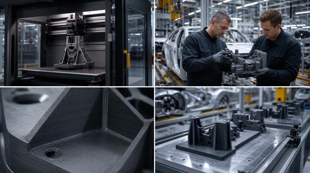
General Motors (GM) has announced that it has expanded its long-standing collaboration with Stratasys to more than 20 manufacturing facilities. According to a 3D Printing Industry article dated 18 September 2026, the automaker uses Stratasys FDM systems not only for prototypes, but also for production tooling, fixtures, gauges and in-plant auxiliary parts. The news is one of the strongest examples of FDM moving in automotive manufacturing from isolated trials to repeatable factory operations.
Where does FDM come into play in GM’s application?
GM teams can produce jigs, fixtures and assembly aids in-house, tailored to specific tasks on the production line. These parts are often not the final components of a vehicle; they are tools that ensure a component is positioned, measured, transported or protected correctly during assembly. Instead of waiting through the conventional procurement process for drawings, quotations, machining, shipping and revisions, the required tooling can be prepared from a digital file through a shorter workflow.
The value of this approach is not limited to printing time; it also becomes clear when designs change. If a fixture does not fit comfortably in an operator’s hand on the shop floor, or its dimensions need to change for a new vehicle variant, the team can redesign and reproduce the same part from scratch. FDM’s layered manufacturing process makes it possible to move forward with low-volume, frequently revised auxiliary equipment without investing in molds or specialized machining.
What the news means for Ucuz3D readers
The GM example does not deliver a generalized message such as “produce everything with a 3D printer.” The real lesson is to define the part’s use case correctly. For tooling used on a production line, dimensional repeatability, rigidity, operator safety and the ability to revise quickly when necessary matter more than surface appearance. For this reason, alongside material selection, infill and wall count, print orientation, connection points and the forces acting on the part should also be evaluated.
PLA or PETG may be sufficient for a simple positioning fixture, measurement template or cable-routing component. However, if temperature, continuous impact, chemical contact or heavy mechanical loads are involved, a more suitable engineering material and a validation process may be required. Before using an FDM-printed tool on a production line, testing it under actual operating conditions, observing critical areas and improving the design iteratively when necessary is a safe approach.
Speed alone is not enough
Although saving time is important in in-plant production, total cost should be calculated by considering filament, printing time, operator labor, post-processing and quality control together. It may not make sense to print every tool in-house. Different manufacturing methods may be more suitable for parts that will be produced repeatedly, require tight tolerances or operate at high temperatures. FDM is particularly strong for low-volume, person- or station-specific auxiliary equipment that changes quickly.
If you have a similar need, you can share the part’s intended use and dimensions to evaluate 3D printing service options. When making material and production decisions, the general properties on our printing materials page can serve as a guide; for budget calculations, you can review the price per gram approach. If your file is ready, you can get an instant quote through the online 3D printing process and turn your prototype or low-volume tooling idea into reality.



 Türkçe
 العربية
 Русский
 فارسی
فارسی Deutsch