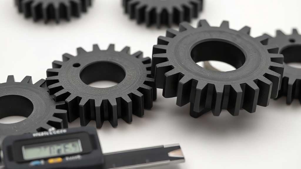

Gear Design for 3D Printing: A Guide to Module, Tooth Count, and Clearance for FDM
A gear that won’t turn, skips, or strips within a few cycles is almost always a design problem, not a printer problem. The three most critical parameters for 3D-printed gear design are module, tooth count, and inter-tooth clearance; get all three right and you can achieve surprisingly smooth-running mechanisms even with FDM. In this post we break down what those numbers on your CAD screen actually become on the print bed.
Module: The Size DNA of a Gear
The module (m) is the fundamental dimension that defines tooth size, and any two gears meant to mesh must share the same module. If you choose too small a module for FDM, the teeth drop below the nozzle diameter and the tooth profile rounds off as if it melted. A practical rule of thumb:
- For a 0.4 mm nozzle, keeping the module at 1 mm or above is safe; this leaves room for at least two or three wall passes at the tooth root.
- In small, precision mechanisms you can go down to a 0.8 mm module, but don’t move to production without first seeing the detail loss on a test print.
- For load-bearing gears, a 1.5–2 mm module works comfortably for both strength and a clean tooth profile.
Tooth Count and Profile Quality
As tooth count decreases, each tooth becomes sharper and weaker; below 17 teeth, profile distortion known as undercutting begins, and in FDM this combines with the already-rounded teeth to cause premature wear. Aim for a minimum of 17–20 teeth on the pinion (the smaller gear) whenever possible. If you want to preserve the gear ratio, scaling up the tooth count on both gears proportionally sharpens the profile and distributes the load across more teeth. Drawing the tooth profile as an involute (evolvent) curve gives a far smoother rolling action than a circular arc; most CAD plug-ins and gear generators do this automatically.
Backlash: Building Clearance Into the Design
Because FDM printing produces slight edge swelling (elephant foot and wall spreading), two gears designed for “full contact” in CAD will lock against each other on the print bed. This is why backlash clearance must be built into the design. Subtracting a total of 0.2–0.4 mm from the tooth thickness across both flanks gives smooth rotation on most machines. You can also open up the center distance slightly to account for this clearance. Rather than relying on generalisations, the most reliable method is to print a small test pair on your own printer and check the mesh by hand.
Print Orientation and Material
Printing the gear flat with the teeth facing up ensures that the layers run perpendicular to the load direction and that the teeth won’t delaminate under stress. Where friction and wear matter, PETG or nylon outlasts PLA significantly; if low noise is a priority, slightly flexible materials absorb vibration. You can compare material options and current pricing on our production pricing page.
When you think about module, tooth count, and backlash together, your gears will work on the first try. If your design is ready or you need professional printing for a mechanism, share your project with us and we’ll produce it with the right material and tolerances.



 Türkçe
 العربية
 Русский
 فارسی
فارسی Deutsch