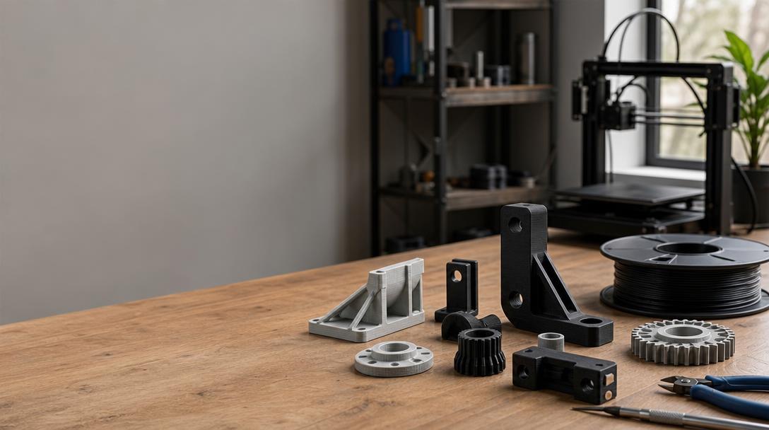

Designing an Industrial Part for FDM 3D Printing: A First Checklist
When designing an industrial part for 3D printing, it is not enough for the part to look correct in the CAD model. What the part will carry, where it will be attached, and the environment in which it will operate also determine its geometry. Because FDM printing builds parts layer by layer, print orientation and thin sections require particular attention. In this first article, we cover the key questions to answer before beginning the design.
Define the part’s function and load
First, describe what the part does: Will it route a cable, position a sensor, or serve as a fixture in repeated assembly? Note whether the part is under continuous or intermittent load, the direction the force comes from, and whether it may be exposed to vibration or impact. If this information is unknown, it is not appropriate to draw definitive conclusions about strength from the design alone; for critical applications, produce a prototype and validate it under real operating conditions.
Choose the print orientation based on the part’s function
FDM parts are built in layers, so the layer arrangement changes when the same model is printed in different orientations. Thin arms, tabs, or projections where the load could try to separate the layers require special attention. Inspect the model in the slicer from several orientations; assess the relationship between layer direction and load, support requirements, and the position of functional surfaces together. There is no single “best orientation” that works for every part.
Check transitions between cross-sections and connection points
Areas where thin sections suddenly meet thicker sections, around screw holes, and sharp internal corners should be highlighted during design review. Where the geometry allows, consider smoother transitions and shapes that distribute the load over a wider area. For screw or snap-fit connections, do not rely on nominal dimensions alone: print tolerances, assembly method, and how many times the part will be taken apart and reassembled all affect the actual fit. Validating critical connections with a small test piece can be useful before printing the entire part.
Match the operating environment to the material choice
Temperature, sunlight, moisture, chemical contact, and the likelihood of wear can all affect material selection. Being “industrial” does not, by itself, mean a filament is suitable for every condition. Clarify the part’s actual operating environment and the properties required; you can review suitable options on the 3D printing with engineering materials page. For more on the relationship between print orientation and strength, also see the guide to the effect of print orientation on part strength.
Plan the first print as a validation step
Before production, check the dimensions, assembly clearances, areas requiring supports, and the part’s movement envelope inside the machine. The first print can be used to test critical dimensions and connections in particular. To have your file assessed for production suitability, learn about our 3D printing service; for a cost estimate, use the 3D printing price calculator. In the next articles in this series, we will take a closer look at print orientation for load-bearing parts.


 Türkçe
 العربية
 Русский
 فارسی
فارسی Deutsch