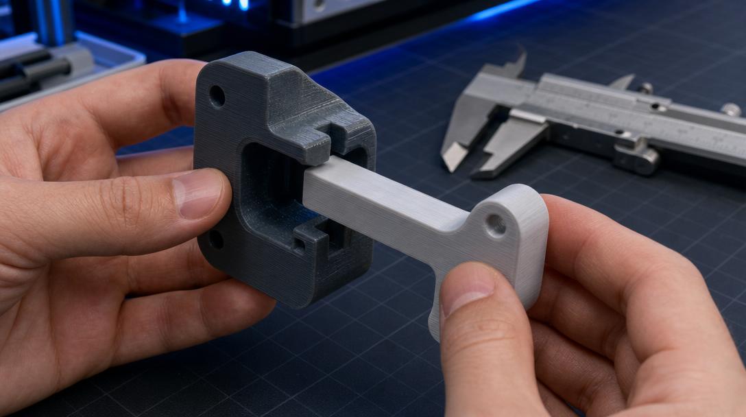

FDM Tolerance Values: The Right Clearance for Interlocking Parts
FDM tolerance values describe how much clearance should be designed into two 3D printed parts that fit together. In practice, for most desktop FDM projects a total clearance of 0.20-0.40 mm is a safe starting range for moving or interlocking parts; however, material, part orientation and printer calibration directly affect the result.
Why nominal dimensions alone are not enough
Drawing two surfaces at theoretically exact dimensions in a CAD model does not mean the printed parts will fit together with that same precision. During the FDM process, molten filament can slightly overflow at corners, holes can shrink a little, and layer lines can increase friction. That is why, for lids, sliders, clips, box covers or interlocking fixtures, relying on the nominal dimension alone often leads to either a too-tight fit or, conversely, a looser fit than intended.
Especially in prototypes, enclosures and functional spare parts, small tolerance differences create a big difference in user experience. For work such as electronic enclosures, snap-fit lids or assembly fixtures, our custom-sized electronic enclosure 3D printing solutions therefore focus not only on the outer dimensions but also on the joining details.
Practical clearance ranges for interlocking parts
There is no single magic number; even so, there are some starting values that work in the field. Beginning your first prototype with the ranges below significantly reduces the number of trials:
- Tight fit: 0.15-0.20 mm total clearance. Suitable for assemblies that seat by hand pressure and do not wobble.
- Standard fit: 0.20-0.30 mm total clearance. A safe range for box lids, clipped housings and everyday functional parts.
- Comfortable sliding fit: 0.30-0.40 mm total clearance. Preferred for sliding covers, rail mechanisms or parts that are frequently removed and reattached.
- Flexible material or large parts: 0.40 mm and above. Gives a safer result with materials like TPU or with large geometries where shrinkage increases.
The term “total clearance” here is important. For example, if you want a 20 mm wide male part to slot comfortably into a female socket, making the socket 20.30 mm can be a good starting point in most projects. However, if you print with PETG a slight tendency to stick comes into play, with ABS or ASA shrinkage behavior, and with PLA more predictable dimensional stability.
4 critical variables that affect tolerance
- Material: PLA is generally the easiest material to control. PETG can behave more stickily, while ABS and ASA are more sensitive to heat management.
- Part orientation: When the layer direction changes, so does the contact surface. Horizontal holes and vertical holes do not behave the same way.
- Nozzle and layer height: A 0.2 mm layer with a 0.4 mm nozzle is balanced for most work; thicker layers can increase surface roughness.
- Calibration: If E-steps, flow rate and first-layer settings are not correct, the fit will be off even when the design is right.
For this reason, printing a small tolerance sample before a critical assembly is the safest approach. If you want to see the cost of repeated trials, you can upload your model and quickly plan small test parts with our calculate your price instantly approach.
A short checklist to reduce errors in design
Tolerance problems are solved not only by printer settings but also by design decisions. Especially in interlocking structures, we recommend adding the following checks:
- Instead of leaving corners at a full 90 degrees, use a small chamfer or fillet.
- On long sliding surfaces, guide the part from several short contact zones rather than a single point.
- Print the first prototype as a small cross-section before the final part.
- For details such as screws, clips and snap tabs, consider the layer direction relative to the load line.
If you want to see more detailed dimensioning logic, the What Is Tolerance? How to Design Interlocking Parts? guide is a good continuation of the topic.
In summary, the right tolerance for interlocking parts in FDM printing is determined more by the use case than by the printer; but the 0.20-0.30 mm range is a solid starting point for most functional parts. If you are unsure about dimensions and material for your own part, share your file and request a quote now so we can clarify the right production approach together.



 Türkçe
 العربية
 Русский
 فارسی
فارسی Deutsch